My Astrophysics PhD Work
So this morning I had an interview and was asked to go over some coding stuff I’ve worked on before. I chose to go over my PhD project at a high level and thought to myself that I should have a page I can point to for this work. Welcome, you’re reading it.
I was busy coaching this weekend so I planned to use a couple hours before the scheduled 10am interview to get everything set up and running again. I was a bit nervous that I’d have enough time to get everything up and running again since it’s been so long, but things worked out just fine. I guess I remember enough and things work well enough.
I’m likely going to make a project page that points to this blog post. The stuff I was working on was always interesting, mostly very cool, and sometimes frustrating. Let’s begin.
A bit about the motivation
Why do we want to build this instrument in the first place? The tldr version of that is: theorists predict certain polarization signatures (properties) for early time light that is headed our way coming from Gamma Ray Bursts (GRBs). If we can get imaging data early enough on a GRB (very short delay from event > imaging, something Skynet, the global network of robotic telescopes is very good at…) and also acquire polariation data from that early time - we can help constrain theoretical models by providing the data necessary to confirm, constrain, or negate several hypotheses about the underlying mechanism at the heart of the explosion. E.g. what is actually going on?
There is of course some noise in this because this package of light on its way to us has been through a lot on its journey, some of which could have affected the polarization signature. However, we’re simplifying that out of our thinking at this point.
This wasn’t the first rodeo
In fact, the name of the telescopes “PROMPT” actually includes polarimetry in the acronym.
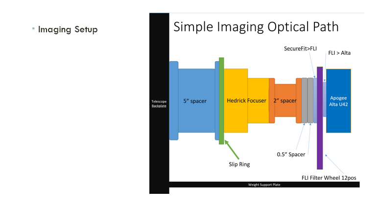
This was the second attempt to build an instrument capable of measuring real time polarization data from an active Gamma Ray Burst (GRB). The first version of the instrument had some limitations we were trying to overcome. The biggest limitation was an all-or-nothing complete takeover of the telescope. This means that acquiring non-polarization data required a hands-on (physical) change to accomplish either by replacing the equipment on a maintenance trip or by asking the local workers to remove and replace the instrument. Not ideal to require hands-on changes to get out of polarization mode. There’s a much higher demand for imaging than there is for polarization imaging, so one of the early parameters was having the polarization components extendible and retractible along the light path such that normal imaging could still take place.
Secondly, the field of view for the image was drastically reduced from the already small 10 arcminutes, and there were regions of the image necessary to discard because of contamination by the optical elements.
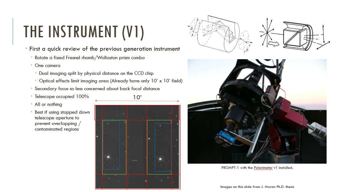
Polarimeter v1
The green highlighted areas were good places to acquire data, and the blue highlighted regions here show matched stars. Finally, the red highlighted areas are to be avoided because of optical distortions.
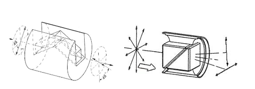
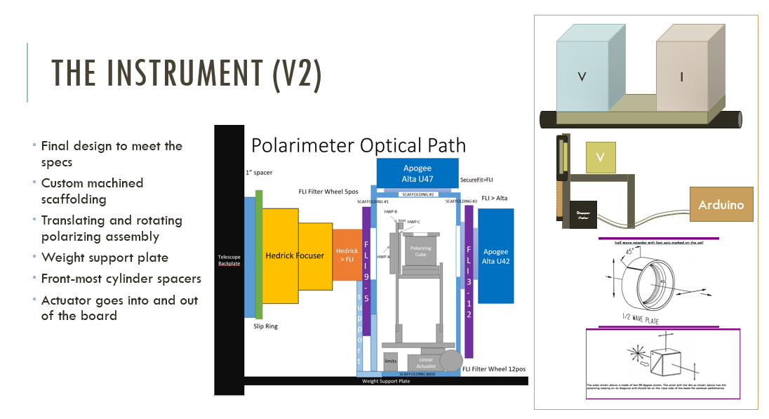
NOTE: vertical and horizontal components are coming out of the same face of the cube.
You can see also how the cube splits the light into its polarized components. If the incoming light happens to be aligned to this cube then great - you’re done, but it’s likely not aligned. So there has to be a rotation of the entire setup such that you fully sample the polarization space.
Now imagine increasing the angle of separation between the two components of the light to 90 degrees and adding a second, orthogonal camera. That’s what I was attempting to make in version 2.
One huge benefit of the first design was the RC design allowing focus to be achieved by moving the secondary mirror instead of trying to move your entire instrument package to achieve focus on a fixed backplane distance focal plane. This would allow you to make a fixed entity that doesn’t move in/out along the focal plane.
A v2.0 design (caveat: fixed backplane distance!)
We tried a lot of things. I say we here because a lot of this work was done by my colleague before I officially took over on the project. Shoutout to Kevin – nice work!
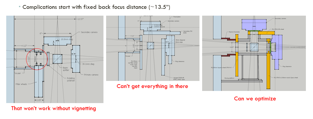
v2 design attempts
Before finally settling on:
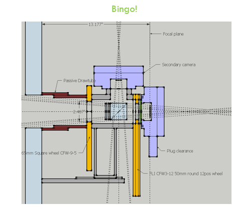
Final v2 Design
I’m simplifying a lot of back and forth and failed attempts at connective hardware to just come out and say that we ended up with this design:
Final v2 Design with Components Shown
Now we have a hardware design
Definitely glossing over a lot about how difficult this was to get everything situated. The biggest problem being that the telescope and imaging equipment was already installed in Chile and was in use every night. I did not have a duplicate of all of the hardware locally which was a terrible idea.
The telescope was installed and operational with this setup.
I learned SolidWorks and also performed some manual drafting in order to interface with the guys in the machine shop. With their help, I was able to complete the custom-built aluminmum scaffolding we needed in order to fit all of these components together. Measure twice cut once is so true.
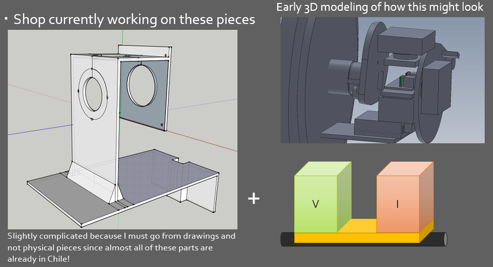
Early SolidWorks imagery of the scaffolding.
A significant amount of work went into getting the physical hardware connections stabilized and connecting together properly. Futher - fitting the optical components in place required extreme caution. Custom pieces needed to be manufacturered because of the complications involved with fitting everything into the backplane distance. Getting proper screws and making sure there the light path is unimpinged and finally that the device can move back and forth inside without also interfering was quite a difficult task, and I made many mistakes.
Without further ado - here’s the instrument on the back of the telescope:
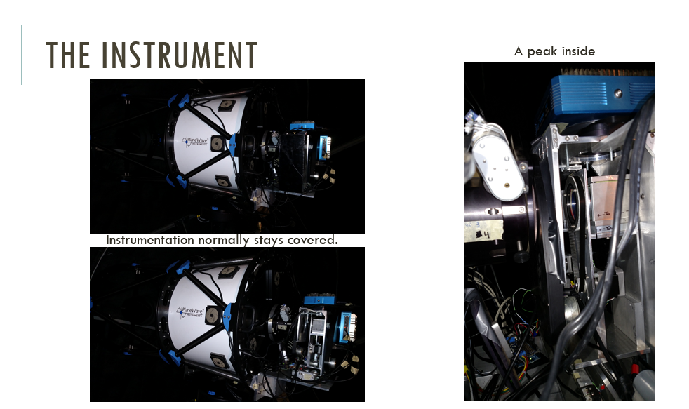
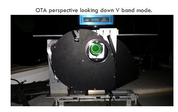
This shows the instrument from a photon's perspective.
This was very much a beta version of the hardware. When I left the program there were several others working on improving the structure integrity and rigidity of the setup. This was how it was when I left. Let’s move on to software now.
Moving on to software.
There are many levels here. From arduino and motor controllers, to simultaneously imaging with both cameras using commercial software, and finally to computing a polarization measurement for the entire frame using image analysis tools.
Let’s talk high level for a minute. In the simplest form, we need a motor to move this imaging package into and out of the optical path. Further - we need a stepper motor to rotate the half-wave plate (special piece of glass) in front of the polarizing cube to rotate the light around so we can fully sample the space. Now, because we wanted a dual band polarimeter - this setup is duplicated, one for V-band imaging and one for I-band imaging. These are common filters in astronomy, and I ordered the optics to match these wavebands, in total there were 2 cubes and 2 half-wave plates from Karl Lambrecht – check out the website for a good time.
When your parts are good, your site can suck.
So we’re going to need 3 motors, a bunch of limit switches, and something to control it all. I chose an Arduino because I was already a little familiar with them and then I found an easily assembled motor shield by Adafruit that let me interface with all of the components I needed to… (almost). I also bought a motor driver for the linear actuator that moved the whole shelf into and out of the optical path.
This work was on my own from assembling and soldering the boards to writing the Arduino firmware and custom serial protocol.
Step 1. Arduino software package
Arduino UNO + Adafruit Motor Driver board, with an added bank of pins for extra grounds for all of the limit switches.
Started with a Vexta motor driver but then moved to the Arduino.
and
The code is open-source, and you can find it on my GitHub. The essence of this code is: set up all of the pins and relevant motor settings in the setup phase, and then wait. However, like all of the autonomous, meant-to-be-remote software operating hardware in the group - it will not do anything unless it knows where its components are, meaning you need to issue a HOME command if the device has been rebooted or has lost its state. We do not want to be issuing moving commands if we do not know where things are situated.
Here’s a video of the homing sequence so you can get an idea of how it works. The front tray of rotating motors rides on the back tray that moves to the center position. Scaffolding is visible.
Step 2. C# GUI to manually interface with the Arduino via the custom Serial Protocol
This shows the instrument from a photon's perspective.
Step 3. Imaging.
We’re using Diffraction Limited’s MaximDL to interface with the astronomical cameras. This gives us a consistent approach to all of the other plug and play software we’re using in the global network of telescopes. With MaximDL version 5 - they finally allowed two cameras to be plugged into the same computer, however, this was meant to be used for a guide camera. That just means there’s a small pick off mirror and a small camera that helps the mount maintain a precise position of that star on those pixels, and adjust as needed in real time.
The problem is that we can’t use that functionality to expose two full frame images at the same time, which is kind of necessary to complete this project at all. We need to expose the two cameras at the same time in order to compare the polarization signature, otherwise if you imagine doing it sequentially there may be a change in the light in the time it takes to wait for one camera to finish reading out before starting the other - it’s just not a good idea.
I tried to ask how to do it on the forums. here is the link
I mentioned Tom How video link 1 and here is another- and his method was what I ended up going with. Two copies of MaximDL on two computers, with a Client/Server acting as the go between.
Step 4. Image Sync
Here’s the result of the Client/Server setup
Step 5. Image Acquisition (Polarization Run)
I’ll come back to this soon.
Step 6. Image Analysis
I’ll come back to this soon.
What did I learn?
A lot.
How to put things together - how to push beyond “that’s not possible” to “here’s how I’ll do it.” Ask for help. I did not ask for help, and I got buried under the amount of work involved in this project. I accomplished a great deal but ultimately did not complete the necessary amount of work to graduate. I completed all of the requirements to graduate except perform novel science with the instrument because that required staying on the mountain for an extended period of time waiting for GRB’s to occur. I don’t have regrets, life moves on. I don’t think I was in the right place for this work, and I don’t think the incentives lined up properly for my advisor to push me out into the world rather than keep me around. I place no blame on anyone. I was simply ready to move my life in a different direction.
Cheers!